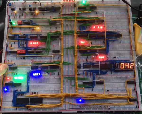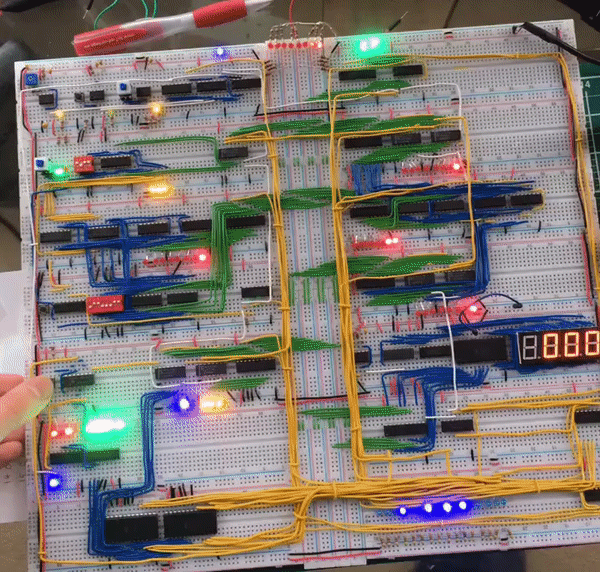
Overview
When I become interested in a topic I often go majorly overboard
with my enthusiasm and background knowledge in an attempt to be as
good at it as I possibly can, this is what happened with
programming and this project. I had the thought that maybe if I
understood more about how the actual bare metal of a computer
worked I'd be able to write better code, as it turns out this
holds some truth, but not as much as I'd hoped.
This started with taking the
nand2tetris course
online and working throught it all, but at the end of it I decided
I wanted more practical experience with computer architecture,
that's where this project and
Ben Eater came
in. Ben Eater is the youtuber who designed this CPU and produced a
series of videos explaining the logic (which I already understood
thanks to nand2tetris) and the electrical sides to the CPU (which
I was sorely lacking knowledge of). And so I decided to follow
along, as I watched I made a list of all the parts needed for each
'module' and took notes of how it all worked making circuit
diagrams where necessary and sourced and bought all of the chips
etc... . It turned out a couple months after I'd finished the
project Ben Eater started selling kits with all the parts needed
to make this, oh well.
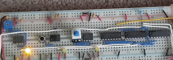
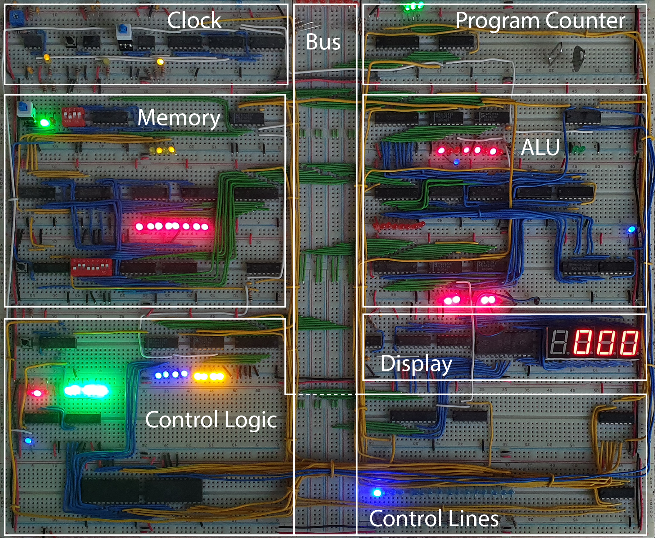
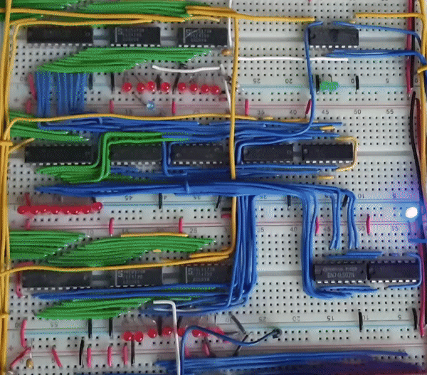
Clock
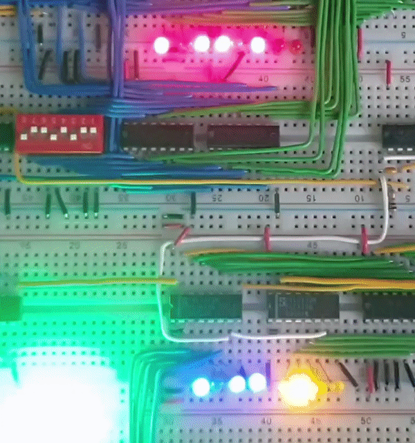
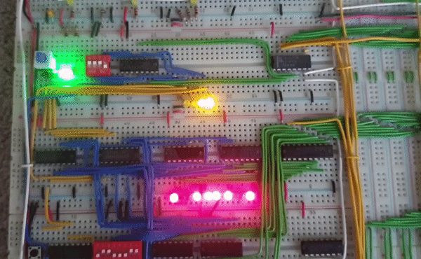
The clock Consists of 2 modes, an auto run mode whose frequency can be changed using a potentiometer and a step mode where each clock cycle is a press of a button. You can switch between these two modes using a toggle switch, as a note both the button and toggle switch are de-bounced using 555-timers to avoid accidental cycles beign performed. The chosen clock signal then goes through an edge detector before being sent to the other modules. The clock lines are shown using white wire.
Instruction Cycles
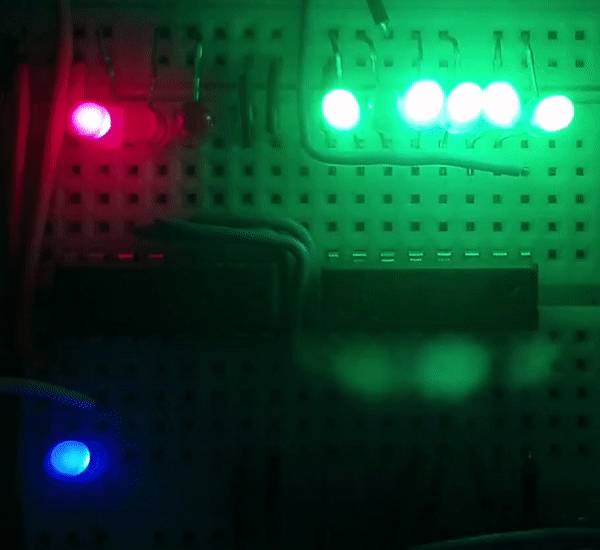
The instuctions for this CPU use a maximum of 6 clock cycles, this is achieved using a 4-bit counter that indicated which stage of an instruction the CPU is currently executing and is incremented every (inverted) clock cycle (shown by the blue LED). We pass the first three bits (shown by the red LEDS) to the decode ROM and to a demultiplexer which defaults high and has the input pulled low so that all except the selected output will be high (shown by the green LEDS) and the 7th output is connected to the rest of the counter so that once the final instruction cycle is used the counter is reset.
Instruction Register
The instuction register pulls its value from the bus and can be broken down into two parts, the instruction bits (shown with blue LEDS) and the address bits (shown with yellow LEDS). The 4 instruction bits determine which instruction is to be executed, resulting in there being a maximum of 16 different instructons, and the 4 address bits can be ouput back onto the bus by instructions that require this, for exmple for loading a literal into the A register or for accessing memory.
Control Lines
The value of the instruction bits + the three bits from the
counter are then used as addresses in the decode ROM which will
then output the desired control lines. The control lines are shown
using yellow wires and the values of the lines are displayed using
a series blue LEDS.
Note: Some of the actual values required for the control lines are
inverted, these are not shown in the series of blue LEDS, instead
if a line is active the line from the decode ROM is set to high
and th put through its corresponding LED and then put through an
inverter before going to its corresponding module.
Memory Modes
The RAM for this Computer is included as it's own module as well
with two modes, Programming Mode(red LED) and Execution Mode(Green
LED), which can be selected using a toggle switch.
Execution Mode works excatly as you'd expect, the memory address
(shown by the yellow LEDs) is determined by a 4-bit register that
is set either by the program counter or a literal from an
instruction and the value at that address (shown by the red LEDs)
is out put when the memory output control line is active.
Programming Mode causes the address to be determined by a
4-position DIP switch allowing the programmer to access memory by
hand. Then an 8-position DIP switch is used to determine the
desired value at a memory address and that value is written with
the push of a button (not automatically), note that writing memory
using this button is disabled in Execution Mode.
ALU
The ALU has two registers an A register (on top) and B register
(bellow) and always automatically sums them but only outputs to
the result to the bus when the ALU output control line is active.
The ALU also has 'extra' arichecture for zero and carry bits. The
zero bit is found by nanding the bits of the alu output in pairs
and then anding those results until a single bit is produced. This
can be seen at the bottom right of the module and the blue LED
there shows the result of that process. The carry flag is simply
the top carry from the adder circuit and is shown by the blue LED
just bellow the A regsiter LED display. These are then connected
to extra circuitry used to determin wheter a conditional jump will
occur (the green LEDS, left is the carry bit, right is the zero
bit).
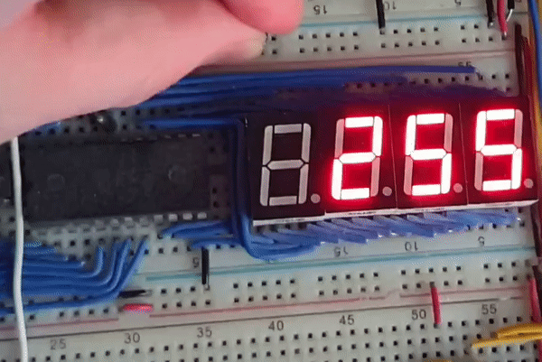
Display
The display always automatically displays whatever is in its
register. Multiplexing is used to display values greater than 1
digit, this required the display to have its own clock.
To determine which display was to be used for each 'display-clock'
cycle a similar method to the instruction cycles was used, except
with a two bit coutner. The output from the multiplexer connected
to the enable pins for each of the displays so for that each
'display-clock' cycle only one of the 7-segment displays is on.
A decode ROM is then used to determine which of the pins for the
7-segment display should be active in order to 'draw' a number.
This ROM used the value in the display register along with the
value of the 2-bit counter as addresses. An extra address bit was
available after this which was used as a 2's complement bit as
seen to the left.