Overview
In my first semester of my 3rd year at University I took a course on computer graphics. In this course I learnt about the algorithms and concepts fundamental to physically based rendering. For the second coursework, we were tasked with building a raytracer using what we'd been taught. We were provided with almost completely empty skeleton code (save for a few abstract classes with unimplemented functions) and were expected to produce a raytracer with:
- A Pinhole Camera and Point Lights
- Plane, Triangle and Sphere Intersection
- Blinn Phong Shading
- Texture Mapping
- Bounding Volume Hierarchies
- Triangle Meshes
- Distributed Raytracing: Thin Lens Cameras and Area Lights
You can view the repository here

Pinhole Camera
The first step was to implement the pinhole camera and use it to generate the rays we will trace.
This involved implementing a transform class that was used for switching reference frames between
the world and camera. Once such transforms were created, the task of generating a ray for a camera
sample was as simple as setting the direction to that from the sample on the virtual film to (0,0)
(the pinhole), ensuring the resulting vector is normalised, and it's origin to (0,0) then transforming
the resulting ray into world space.
I then simply made a loop that ran through each pixel, taking a sample from the camera for each, and then
setting the colour of that pixel to the background colour (as no intersection has yet been implemented).
Plane, Triangle and Sphere Intersection
To simplify my job, I decided to work on shape intersection next. This involved transforming the incoming rays
into the object's space, and then finding the parametric value of the ray (t*direction + origin) at which the ray
intersects with the object. If the ray doesn't intersect with the object, the value will be inifite. Additionally
if the ray interacts with the object twice (such as is necessary for all rays that hit and aren't tangent to a sphere),
then we only care about the smallest value (closest intersection).
Again to simplify my job, once I'd implemented the triangle intersection, instead of finding arithmetic for plane intersection,
I simply created planes as two triangles and passed the intersection test to those triangles.
When tracing rays I tested intersection with all the objects in the scene, storing a list of all intersections that hit objects.
I then found the intersection in that list with the smallest parametric value, and set the colour of the pixel to the diffuse colour
of that object.
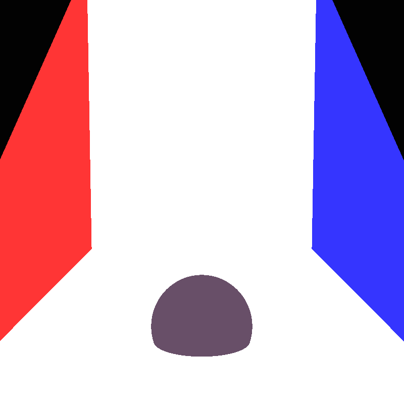
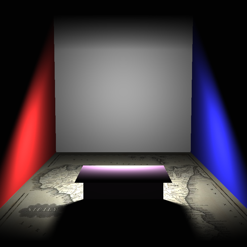
Point Light
I was now able to start working on shading with the point lights in the scene. This was a simple task, the distance from the intersection
point to the point light was found and used to calculate the intensity of the light at that point, the colour of the object was then scaled
by that value.
Doing this alone resulted in a very strange looking result with radial artifacts centered around the light. The solution to this was to apply
tonemapping. I looked at many methods of tonemapping, but due to time contstraints decided to simple clamp all pixel colour values to the (0,1)
range, as that models how a real (simple) camera sensor would work.
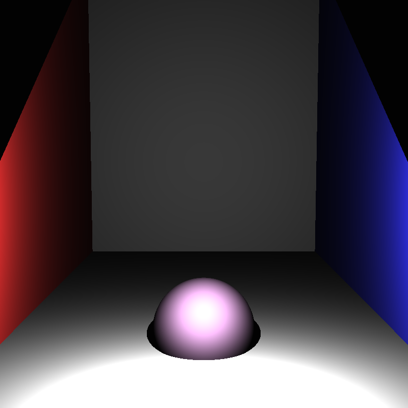
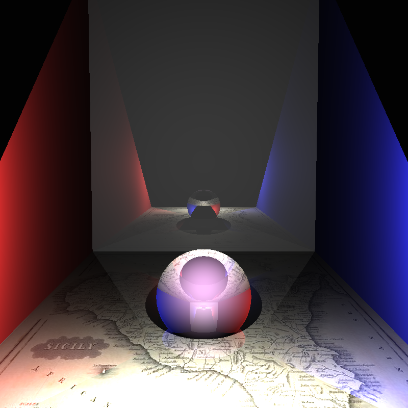
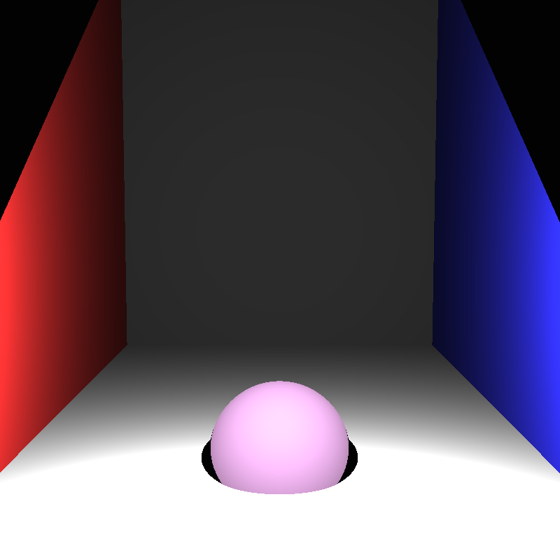
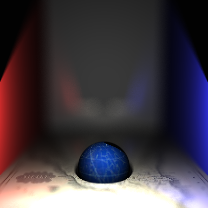
Blinn Phong Shading
Blinn Phong is a shading technique that models the diffuse and specular interactions between light and the objects. Implementing this took a lot
of trial and error, as there are many different equations for calculating blinn phong onine. In order to implement this correctly I had to return
the surface normal of an intersection aswell as the calculated parametric value.
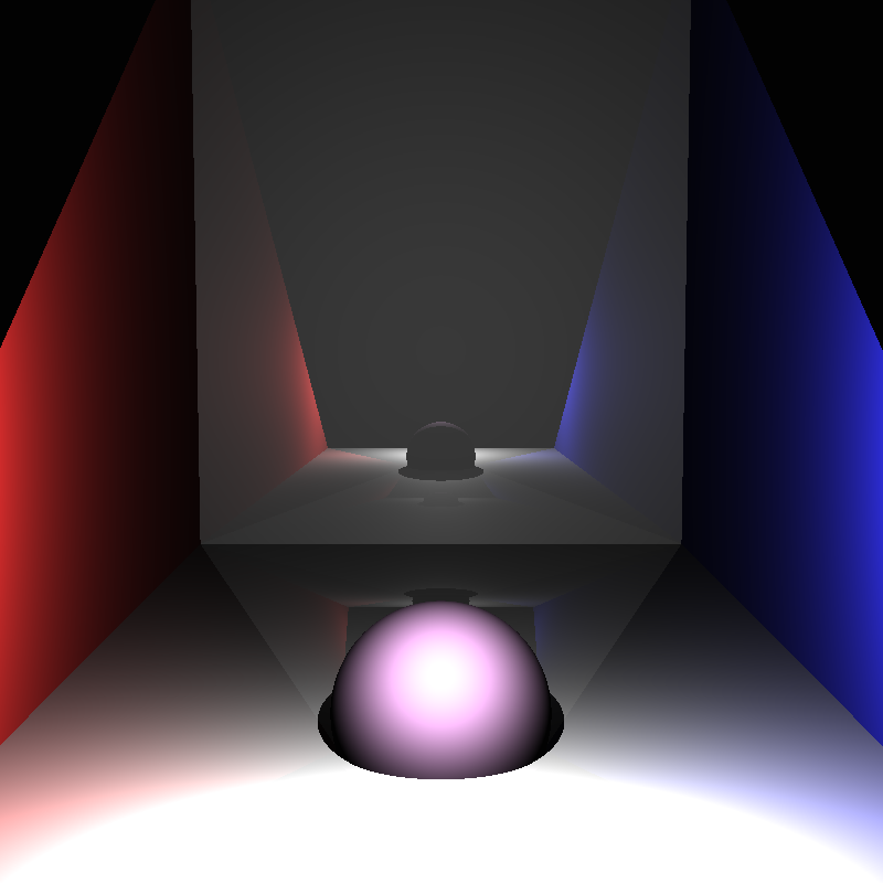
I also implemented reflections and refraction at this
stage (Note: the refraction reference image was generated after implementing texture mapping).

Texture Mapping
Texture mapping again involved incorporating extra data in the results of an intersection, in this case the uv coordinate of the intersection. This coorindate system maps the surface of the object to the range [0,1]2. The coordinates can then be used to select a pixel from a corresponding texture which shall be used as the diffuse colour of the object.
Bounding Volume Hierarchy
A bounding volume hierarchy (BVH) is a method for accelerating intersection testing, it involves splitting the objects into two partitions,
creating a bounding box for those paritions, then repeating as if each partition was the entire scene, until there is only one object left.
This produces a binary tree.
The method of paritioning the space I used was to pick n (16) equally spaced partition lines on the axis with the larges range, and then
find all the partitions for each, and use the partition point that incurs the smallest cost. Cost here is measured using the sum of surface
area of each partition over the surface area of the entire scene.
I was unable to measure performance gain from using this BVH, though I would not have been able to render my triangle meshes without it
(I never completed a render).
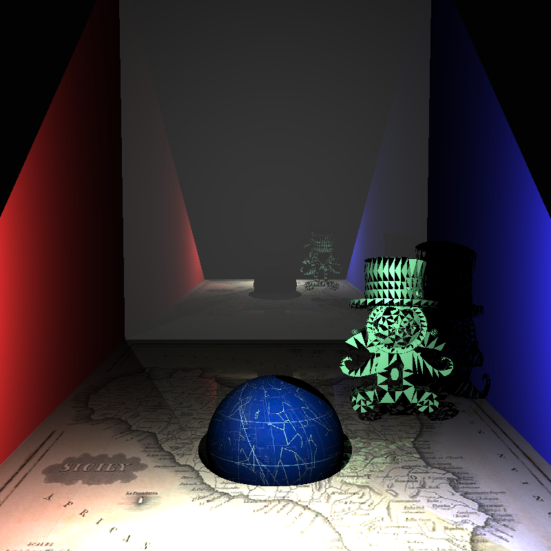

Triange Meshes
Implementing triangle meshes was easier than I had expected. I was able to find a header library that would handle opening .ply files for me
, at which point I simply had to run through the data creating triangles, storing them in a list and then using said list to create a BVH.
However I did still encounter issues; to begin with, some ply files used quads, resulting in missing faces; and then there was the matter of
correctly calculating surface normals and texture coordinates. These both had the same solution, each vertex had a normal and a texture cordinate,
finding the weighted sum of these normals/coordinates using the barycentric coordinate of the intersection, provided the correct value, as can be
seen from the smooth shaded and textured examples.
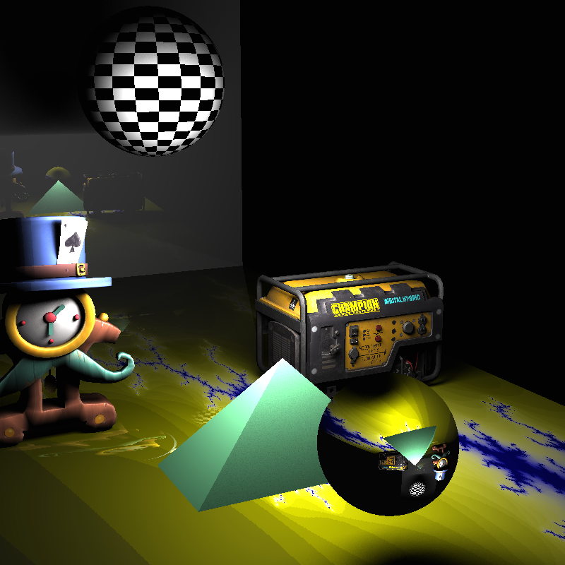
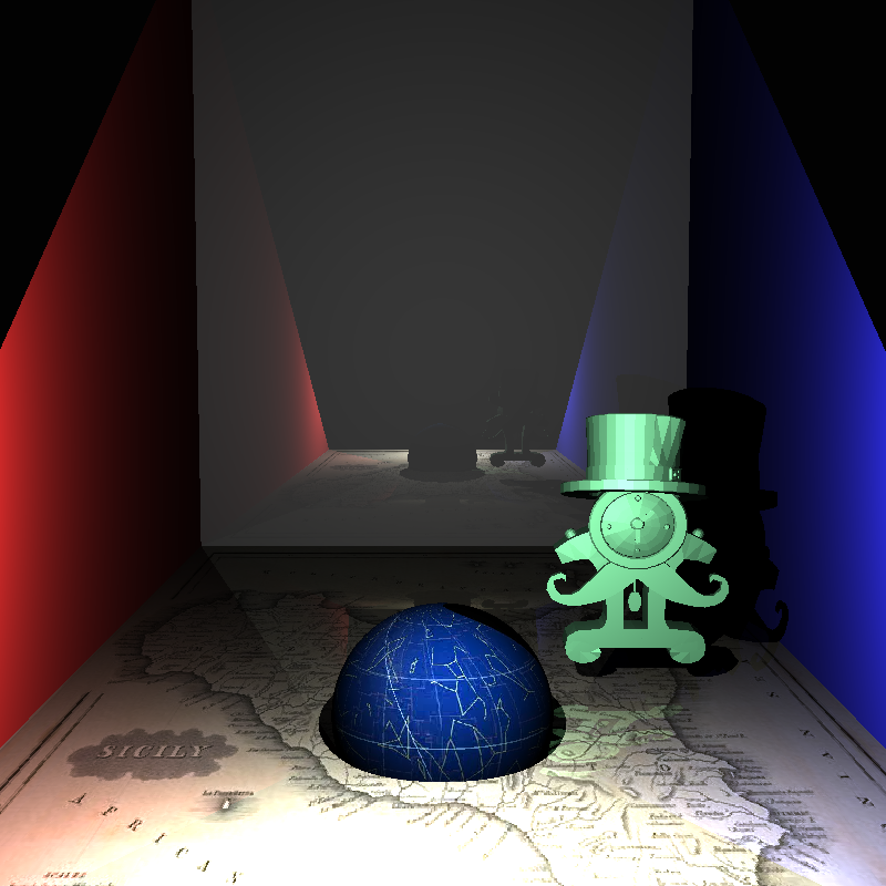
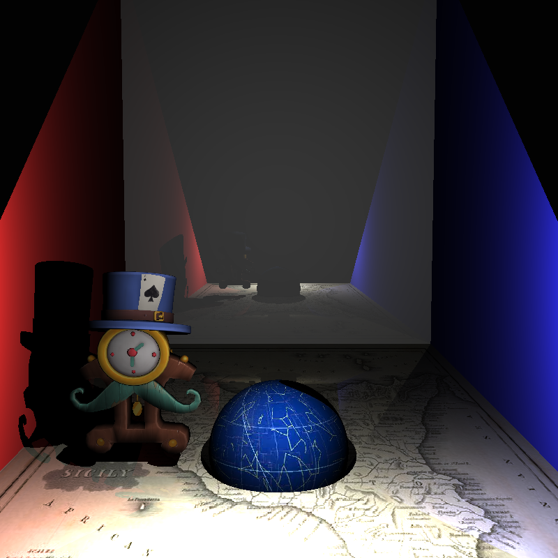
You may notice the lighting is off on the last two example images, I accidentally scaled down the normals (resulting in dimmer lighting) and needed to
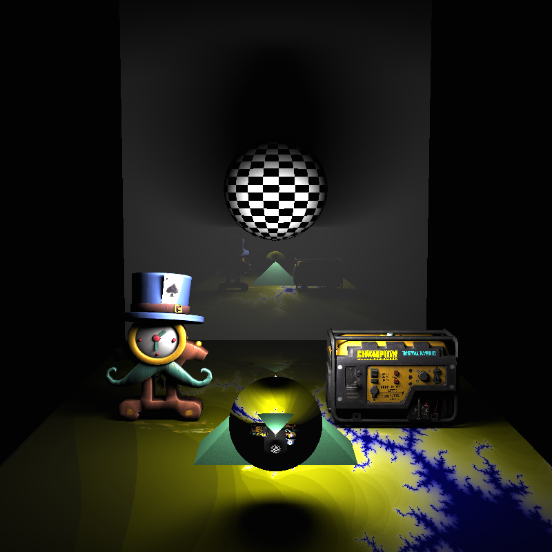
implement self shadowing correctly for triangle meshes. Both of these issues were fixed in my final version at the bottom of this page, this is exemplified
by the shadow the card casts on the hat, the shadow the hat casts on the clock and the shadow the rim of the clock casts on the clock face.
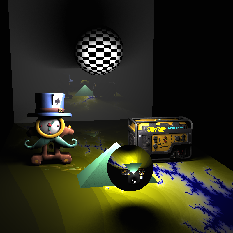
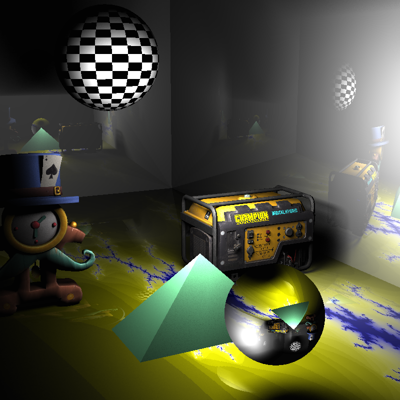
Distributed Ray Tracing
Distributed ray tracing, is effectively, where you use intergration of some kind within your raytracing. The best example of this is the area light, where the lighting has be calculated from across the whole surface of the light rather than a single point, taking into account how much of the surface is obstructed, the result is soft shadows. Similarly thin lense cameras take samples of rays from all over the lense and average their colour to produce the pixel value, this can result in a depth of field effect.